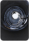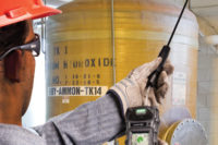
When monitoring in a duct for gas hazards, several factors should be considered, including the sampling conditions, gas characteristics and flow dimensions, in order to obtain a meaningful gas measurement. You must ensure, of course, that the sensor is not installed in conditions that will damage or hinder the sensor’s capability to detect gas. This article will weigh the merits of in-situ (localized) sampling in the duct versus pumped sampling based upon sample conditions.
Start by determining the following sample conditions: temperature, particulate load and the potential for condensation. Sensors have defined temperature limits, and if those limits are exceeded, you should pump out the sample and allow it to cool to ambient temperature.
If there is a high particulate content in the duct, a monitor’s reliability may be compromised if it does not receive the necessary maintenance. In general, pumped sampling is the preferred method in areas of high particulate content. This concept, and that of temperature limits, will be discussed later in further detail.
If the sample gas could run close to the dew point of one of the duct’s stream components, you must take steps to ensure that liquids do not deposit on the sensor’s face. This is especially important for explosion-proof (XP) assemblies, which have a porous metal flashback arrestor that can hold the liquid and completely block gas diffusion. A water-repellant disc in the sensor guard of the duct mount assembly can provide some protection if the liquid is water-based. If pumped sampling is used, allow enough tubing to cool the sample to ambient temperature and collect the liquid in a coalescing filter just before the sensor. A hydrophobic filter is a good backup for the coalescer.
Sensor placement
Sensor placement is a critical aspect when monitoring in a duct. Place the sensor in an area that has a representative gas stream and place it such that calibration gas can be delivered to the sensor. If the ambient flow is too great in the duct, calibration gas will be swept away before the sensor can obtain a proper reading. If the sensor is not placed properly, there will be no correlation between the calibration gas reading and the actual gas concentration.Depending on the geometry of the duct and the densities of the sample’s components, stratification and layering may exist in the stream, because long, straight runs in the duct can produce a gradation effect. Variations may also occur in the material flow due to friction with the duct wall, causing the gas flow in the middle of the duct to move faster than along the wall. This effect may cause some composition variations in the cross-section of the sample. Ideally, some mixing of the sample is desirable to ensure sensing of everything present in the duct.
Too much turbulence can sweep away all of the calibration gas or trap the sensor in an eddy that is isolated from the bulk of the sample. The best location for the sensor is at a point after the turbulence has taken place to ensure that the sample is well mixed. However, the sensor should not be placed in the middle of a violent flow.
The sensor should never be placed in the branch of a tee, as it could be out of the main air stream. A tee branch could potentially be a dead leg that never has gas exchange with the duct flow and is therefore not representative of the gas stream running through the duct. A good rule is to place the sensor after a turn in the duct, or after it has expanded to a larger size after multiple streams are brought together. Placing the sensor in this location forces sufficient mixing of the flow patterns without excessive turbulence.
Always consider convenience of the installation. It may not be practical to install the unit in the preferred position, which is on the top of the duct with the sensor facing down. An alternate mounting position is to lay the sensor sideways on the side of the duct. It is never acceptable to have the sensor facing up in this position, as particulate or condensate could cover the face of the sensor and block gas diffusion.
Infrared or catalytic?
Choice of sensor type should be carefully evaluated in combustible gas duct mounting applications. Three important factors to consider for monitoring combustible gases in ducts are gas composition, sample conditions and the nature of the gas sample.First, consider the gas composition itself. Is there oxygen in the background? The catalytic sensor requires oxygen to complete its reaction, while the infrared sensor can operate in a completely inert background. Additionally, any silicone compounds in the sample could deactivate the catalytic sensor and such applications, therefore, require an infrared sensor.
Second, consider sample conditions such as temperature and particulate load. The infrared sensor is close-coupled to its controlling electronics and has limitations on temperature tolerance. The catalytic sensor runs hot with a high pelement surface temperature, withstanding heat much more readily. The catalytic sensor can be separated from the electronics, allowing the sensor to be used at temperatures of up to 150ºC. If the sample is high in particulate, the infrared sensor is a better choice because it has no porous metal flashback arrestor that can become dust-clogged. Additionally, the point infrared sensor gives a fault signal if the optics become obscured by dirt or liquids, a feature that catalytic sensors cannot offer.
Finally, evaluate the gas sample itself. Catalytic sensors generate a signal with any gases or vapors that burn, including many hydrocarbons, hydrogen, CO, H2S and NH3. Compounds with a flashpoint above 110ºF cannot be reliably detected with a catalytic sensor, due to incomplete combustion and soot formation. Infrared sensors typically only respond to hydrocarbons accurately (not hydrogen, CO, H2S or NH3), as they operate by counting carbon-hydrogen bonds. If any of the molecule’s hydrogen atoms are substituted with another type of atom (such as chlorine, double-bond, etc.), spectral characteristics are changed and the response is reduced. This may make some hydrocarbons (for example, methylene chloride or benzene) difficult to detect with the point infrared combustible sensor.
In-situ duct sampling offers the advantages of real-time measurements, a minimum of components to maintain and ease of installation. Conversely, a pumped system can often be used when sample conditions are not conducive to perform in a localized setting.
