How to de-energize equipment
Force guided relays maintain machine guarding circuit integrity

Safety circuits used in machine guarding applications incorporate devices such as sensors and relays to de-energize equipment if any hazardous condition is detected. These conditions normally involve a machine guard not being closed, a presence sensor detecting personnel in an unsafe area or the triggering of an emergency stop function.
It is also possible for the actual safety devices used, such as relays, to experience an internal fault, and force guided (FG) relays can be used to detect this condition.
FG relays are a special category of control relays for use in safety circuits. Their configuration allows them to be monitored by the safety circuit, so if a relay failure is detected the circuit can attempt to shut down and prevent re-starting the protected equipment.
For systems with many motors or powered devices that much be de-energized by a safety circuit, FG relays are the safest way to expand the number of outputs. This article will discuss how FG relays work, the features users should look for and the best way to incorporate them into applications.
What is a Force Guided Relay?
A mechanical control relay uses the electromagnetic force produced by its energized coil to physically move its switched contacts. This allows a relay to monitor a single input circuit and “relay” its status to one or more output circuits.
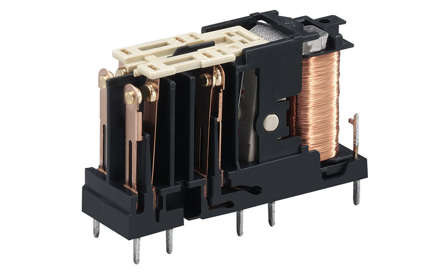
Several design features distinguish FG relays from general purpose relays (Figure 1):
- Individual contacts
- Electrically isolated contacts
- Mechanical guide mechanism linking the force between contacts
- Specific monitoring contact
These features indicate if a failure occurs. One failure mode is if any set of electrical contacts welds, which occurs when high current creates heat that fuses the contact together and prevents it from opening. Another common failure mode occurs when a contact leaf breaks. Together, these features provide failsafe operations for safety circuits.
Electrical contacts commonly come in three arrangements:
- Normally-open (N.O.): Also known as Form A, closes when relay is energized and open otherwise
- Normally-closed (N.C.): Also known as Form B, opens when relay is energized and closed otherwise
- N.O./N.C: Also known as Form C, two contacts (one N.O. and one N.C.) sharing a single common contact
General-purpose relays may have many different contact arrangements, but FG relays will only use individually isolated N.O. or N.C. contacts, with each contact performing one function -- either power control or monitoring. An FG relay will usually have one or more N.O. contacts for controlling other circuits, and one N.C. contact for a monitoring circuit. When the circuit is safe the FG relay will be energized and the N.O. contacts will pass power to the protected component, while the N.C. contact will interrupt power to the monitoring circuit.
Electrical isolation in FG relays is achieved because each contact resides in its own compartment, physically separated from the others. FG relays get their name from a special mechanical interlocking linkage which connects the moving part of each contact. During actuation, all contacts must move in tandem. If any contact welds and fails to move, the linkage bar prevents the other contacts from shifting as expected. The safety circuit uses the monitoring contact to detect this type of weld failure.
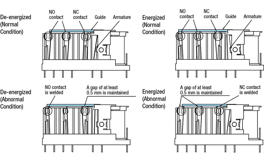
There are four possible states (Figure 2):
- Normal de-energized
- Normal energized
- Abnormal de-energized
- Abnormal energized
A final feature of FG relays is the N.C. monitoring contact. The safety controller operating the FG relay is also connected to this monitoring contact. The controller compares its status against the commanded position to identify any mismatch and acts upon this abnormal condition. Even if one controller operates many FG relays, all the monitoring contacts will be wired in series to detect any failure.
Key features
When choosing FG relays, OEM machine builders and end users should look for the following key features:
- EN50205 compliance
- Fast response time
- Coil surge suppression
- LED indicator
- High operating shock resistance
Due to their critical service nature, FG relays must be compliant with a specific industry standard, EN50205, which defines the characteristics and testing of these devices.
A fast response time is recommended, typically better than 10ms. Also, because FG relays are often driven by solid-state controllers, good practice calls for the FG relay coils to be provided with counter-electromotive force provisions so any power surges from the coil will not damage the controller.
Output expansion
While beyond the scope of this article, various industry standards from IEC and ISO define the safety requirements for a range of automation applications. Standard ISO13849-1 defines how a performance level (PL) is determined using parameters such as a category ranging from B to 4. Based on this, various applications may require progressively more stringent features for contact monitoring, input redundancy and output redundancy. Most safety circuits are designed to at least category 2, with provisions for checking for loss of safety functions required. FG relays, with their interconnected contacts and monitoring contact, are an excellent way to provide this functionality.
Conclusion
FG relays are a key component used in safety circuits. They are especially useful for the typical case when designers need to expand the output from one safety controller or relay to interlock multiple motors and other equipment types in a machine guarding application. Understanding of how FG relays operate and the key features to look for enable designers to choose the best options for their machine guarding applications.
Looking for a reprint of this article?
From high-res PDFs to custom plaques, order your copy today!