Machine Safety

More than ever, as automation continues to permeate the industrial workplace, interlock switches are playing a key role in machine safeguarding. These safety devices are especially important in automated factories where a variety of complex products such as automobiles, computers, electronics, and food and beverages are produced at lightning-quick speeds.
With so many variations of interlock switches available today, each with distinct characteristics designed to satisfy different application needs, safety pros need to familiarize themselves with the general features and requirements that make a device suitable for interlocking duties.
Basic requirements
As for standards, the European Standard EN1088 (ISO14119), “Interlocking devices associated with guards,†provides a good deal of guidance. This standard is to be considered in conjunction with EN 60947-5-1 (IEC 60947-5-1) for electromechanical switches.Additionally, ANSI is expected to release this spring a new revised Z244.1-2003 standard, “Control of Hazardous Energy – Lockout/Tagout and Alternative Methods.â€
An interlock switch must operate reliably even under extreme conditions and rough treatment. The operating mechanism should be kept as simple as possible. All materials used in its manufacture should be of the highest quality, the design should ensure that component wear is kept to a minimum, and the mechanism should be enclosed in a strong, sealed case.
The security of an interlock switch is dependent on its ability to withstand attempts to defeat the mechanism. In some circumstances, personnel may be tempted to override the switch in some way. Information concerning the use of the machine, gathered at the risk assessment stage, will help to decide whether this is more or less likely to happen. The more likely it is to happen, then the more difficult it should be to override the switch or system. The level of estimated risk is also a significant factor that needs to be considered. Switches are available with various levels of security ranging from resistance to impulsive tampering, to being virtually impossible to defeat.
In applications where a high degree of security is required, it is sometimes more practical to achieve this with unique mounting configurations. For example, mounting the switch with a covering track eliminates access to the switch with the guard door open. The nature of any “cheating†prevention measures taken at the installation stage will depend on the operating principle of the switch.

Positive mode operation
EN 292 (ISO12100) explains that if a moving mechanical component inevitably moves another component along with it, either by direct contact or via rigid elements, these components are said to be connected in the positive mode (a.k.a., direct operation).With single mechanical type interlocking switches, when the guard is opened, the movement of the guard should be connected in the positive mode to the safety contacts of the switch. This ensures that the contacts are physically pulled apart or “force disconnected†by the movement of the guard.
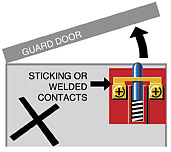
The switch should not rely solely on spring pressure to open the contacts, as the force exerted may not be able to overcome sticking or welded contacts. There is also the possibility that the switch could fail to danger if the spring breaks and there is no other way to open the contacts.
Figure 1 depicts a typical negative (or non-positive) mode operating system. There is no direct link between the guard door and the safety contacts, so the system relies entirely on spring pressure to open the contacts. In the event of spring failure, contact weld or sticking, the system will fail to danger and is therefore unacceptable. Pushing the plunger while the guard is open also easily defeats this type of system. Even worse, an operator leaning onto or into the machine while the guard is open can trip the switch accidentally.
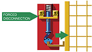
Figure 2 illustrates a simple example of positive mode operation giving forced disconnection of the contacts. A cam is mounted on the door hinge so that it directly operates the contacts whenever the guard door is open. Spring pressure can only close the contacts when the guard is fully closed. Any spring breakage will only result in a failure to a safe condition.
Enclosure
The positive mode operation principle shown in Figure 2 is used wherever it is relevant in safety interlock switches. This also avoids any possible abuse by enclosing the contact block and cam in a strong and secure enclosure. This means that the cam and the contact block cannot become separated, and it is impossible to defeat the switch by cutting another slot in the cam.
The principle is adapted further for actuator-operated interlock switches as shown in Figure 3. These devices are widely used because they are simple to mount at the opening edge of the guard, and can be used on sliding, hinged and removable guard doors. The actuator is mounted on the guard door, and opening the guard causes it to force-disconnect the contacts. The switch mechanism is enclosed and is designed to resist tampering.
Other safety principles
As a minimum, all designs and materials must be able to withstand the expected operating stresses and external influences.
For non-mechanical devices, there is usually no physical contact between the switch and actuation method. Therefore, positive mode operation cannot be used as the way of ensuring the switching action, requiring the use of other methods.
Oriented failure mode
With simple devices, components with an oriented failure mode can be used as explained in EN292-2 (ISO12100-2). In practice, this means using components in which the predominant failure mode is known in advance, and is always the same. The device is designed so that anything likely to cause a failure will also cause the device to switch off.
An example of a device using this technique is the MA Series non-contact magnetically actuated interlock switch from STI. Being in series protects the contacts with an internal, non-resetable overcurrent protection device. Any overcurrent situation in the circuit being switched will result in an open circuit at the protection device, which is designed to operate at a current well below that which could endanger the safety-related contacts.
Duplication (a.k.a. redundancy)
EN 292-2 (ISO12100-2) explains that if components that are not inherently safe are used in a design, and they are critical to the safety function, then an acceptable level of safety may be provided by duplication of those components or systems. In case of failure of one component, the other one can still perform the function. It is usually necessary to provide monitoring to detect the first failure so that, for example, a dual channel system does not become degraded to a single channel without anybody being aware of the fact. Attention also needs to be given to the issue of common cause failures.
Any failure that will cause all duplicated components (or channels) to fail at the same time must be protected against. Suitable measures may include using diverse technologies for each channel or ensuring an oriented failure mode.

Galvanic isolation
Lastly, on contact blocks with two sets of contacts, a galvanic isolation barrier is required if it is possible for the contacts to touch each other back-to-back in the event of contact weld or sticking (Figure 4).Looking for a reprint of this article?
From high-res PDFs to custom plaques, order your copy today!


.webp?t=1721257160 "download (1).jpg")
