Emergency Shower Recirculating Loop Considerations
When multiple people could be exposed at the same time
In the event of an emergency, facilities must be prepared to respond to various potential dangers or crises. Facilities that work with caustic materials are required by OSHA to provide suitable facilities for quick flushing of the eyes, face and/or body. If there is an instance multiple employees could be concurrently exposed to a hazard requiring the use of drench equipment, then all emergency shower and eyewash units must be capable of running simultaneously while still meeting pressure and flow requirements. Many times the emergency shower and eyewash units run on a recirculating loop system.
When designing and laying out the piping loop for a recirculating tepid water system for a series of emergency showers, there are a number of important items to consider to maximize the performance and minimize the cost of the required tepid water delivery system.
Common configurations and their characteristics
Recirculation pump only
Description: Small recirculation pump runs all the time at 5-10 GPM.
Common characteristics:
- Relatively short loop length and/or relatively high-inlet pressure available;
- Inlet pressure is sufficient to overcome skid piping, loop piping, and elevation losses and still provides at least 30 PSIG at last shower and eyewash units on loop during operation;
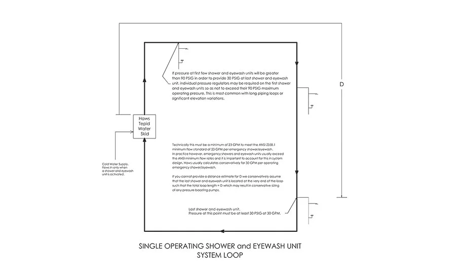
- Single shower and eyewash unit operation loops (activation of only one shower and eyewash unit at a time required).
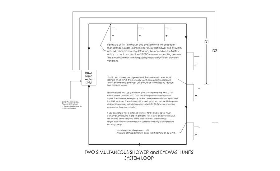
Recirculation pump with separate booster pump (see Figure 1 above)
Description: Small recirculation pump runs all the time at 5-10 GPM until a shower/eyewash is activated, at which time the recirculation pump switches off and a larger booster pump turns on to provide additional pressure and flow to the shower and eyewash units on the loop so the last and/or second to last shower and eyewash unit on the loop is provided with at least 30 PSIG during operation.
Common characteristics:
- Moderate loop length and/or relatively low-inlet pressure available;
- Inlet pressure is NOT sufficient to overcome skid piping, loop piping, and elevation losses and still provide at least 30 PSIG at last shower and eyewash unit on loop;
- These are loops that require two shower and eyewash units must be able to operate simultaneously.
Combination recirculation pump and booster pump
Description: Recirculation pump and booster pump run continuously at a flow rate and pressure sufficient to provide the required flow for one or more shower and eyewash units as required by the system.
Common characteristics:
- Long loop lengths, often requiring larger diameter pipe;
- Outdoor loops that can lose/gain heat to/from the environment at lower flow rates;
- These are loops that require one or more shower and eyewash units to be able to operate simultaneously;
- Variable Frequency Drives (VFDs) are sometimes used with these pumps to accommodate system variables and match flows to one or more shower and eyewash units. A VFD can also prevent issues caused by variable inlet pressures.
- Sometimes small recirculation/booster pumps are used in a single shower and eyewash unit if the inlet pressure is such that only a small amount of boost pressure is required and the difference in size between a recirculation pump and the booster pump required is small. This can sometimes eliminate an extra pump.
General considerations
- If the system must support two simultaneously operating emergency shower and eyewash units, minimize the distance D1 (see Fig. 2 above) along the piping between the tepid water delivery skid and the second to last shower and eyewash unit on the loop. It is generally better, where possible, to place shower and eyewash units on the outgoing half of the recirculation loop, rather than on the returning half of the recirculation loop. This minimizes the pressure drop for the highest flows required (worst case being the second to last and last shower and eyewash units on the loop being activated simultaneously, with the full flow being required at the distance of the second to last shower and eyewash unit on the loop).
- If a system must support two simultaneously operating emergency shower and eyewash units, use at least two-inch diameter piping. Use a pipe diameter such that the pressure loss due to friction and elevation change does not exceed 30 PSI at the maximum flow rate that might be required in the piping between the skid and any shower and eyewash unit. This is typically the worst case at the second to last shower and eyewash unit in a system without significant elevation change, but there may be another shower and eyewash unit where significant elevation changes are required. For Schedule 40 galvanized steel pipe in a level loop, a very rough guide might be to use two-inch diameter pipe where D1 (see Fig. 2 above) distance is up to 650 feet (198 m), and three-inch diameter piping where the total loop length is up to 4,400 feet (1341 m).
- Strongly consider installing air eliminators at any high points in your loop. Entrained air accumulates in a recirculating system and can cause poor recirculation performance. These are low-tech, inexpensive devices that can prevent many hard to diagnose problems.
- Supply the tepid water delivery skid with as high a constant water pressure as possible up to 90 PSI. This minimizes the size of the booster pump that may be required. If water pressure varies between 30 PSI and 60 PSI, the size of the pump is then based on the lowest pressure in the PSI range. A higher constant pressure is best.
- Recirculation loop piping exposed to outdoor, extreme conditions should be well insulated or heat traced. This minimizes the size of the water heaters required to counter heat losses through the piping, and reduces the start-up and recovery times required.
- Burying long lengths of non-insulated recirculation loop piping is not recommended. The same massive heat sink qualities that make burying pipe a great solution for keeping water from freezing by keeping it closer to the natural soil temperature can make it a detriment to keeping heated water in the piping. This can lead to the requirement for substantially larger heaters with constant high current draws. The thermal conductivity of local soil is a major variable which is seldom well known and can make a system that looks good on paper perform poorly or inadequately in applications. Where loop piping must be buried, consider using an appropriate underground pipe insulation.
- Where recirculation loop piping layout requires that water leave the skid at pressures in excess of 90 PSI in order to reach the last shower and eyewash unit at 30 PSI as required by ANSI Z358.1, individual pressure regulators may be required on emergency shower and eyewash units close to the tepid water delivery skid.
- Whenever possible, provide an expected layout diagram of your recirculation loop with pipe diameters, elevations, and distances between shower and eyewash units and an expected tepid water delivery skid location. With this information, a good estimation for pressure and heat losses, as well as pump and heater sizing, can be made.
- If a recirculating loop is large and complex, or not well defined, a variable frequency drive (VFD) may need to be specified on the booster pump(s). This technology adds flexibility that can help mitigate many poorly defined variables and facilitate unforeseen changes to loop piping or pressure availability.
Looking for a reprint of this article?
From high-res PDFs to custom plaques, order your copy today!