Gas detection systems
In times past, gas monitoring systems were free-standing, and any data they generated was collected and used on a local basis. Today, plants and other facilities most likely require that all data be centralized so monitoring systems can perform their functions and provide data to higher-level systems. Data must be accessible on plant-wide backbones, which come in many flavors.
In addition to various proprietary data busses, some plant backbones are serial-based (Modbus RTU, DF1, Metasys), many are based on Ethernet architecture (Modbus TCP, EtherNet/IP, BACnet/IP) and others are based on fieldbusses such as Profibus, DH+ and ControlNet. This discussion is confined to serial data busses and Ethernet networks, but the principals and issues are universal.

A strong backbone
The challenge for industrial hygiene professionals is to determine which backbone interface is required and then ensure that the selected equipment meets that requirement.Figure 1 represents the minimum requirements for a gas detection system that are generally well understood. The system must include gas detection modules, a method to communicate to a controller, flexible alarm handling with relay outputs, and a method for communicating data to higher-level systems. In this case, serial communications are used to provide data to a dedicated computer.
For purposes of meeting future requirements to integrate data to a facility backbone, this minimum system with serial communications is now well on the way to plant-wide integration. At the Control level the system provides sensor monitoring and also controls the alarm activities. At the Information level data can be retrieved from the controller via the serial connection. The facility IT group, plant process control team or the building automation consultants are now free to investigate opportunities to interface to the gas detection system via the plant backbone.
The terms “serial communication†or “Ethernet†describe only the electrical hardware characteristics of the backbone, such as the type of wires and the methods of connection. Comparing to an office equipment environment, a serial connection would interface a computer to a modem, while an Ethernet connection would network the computer and allow it to communicate with a server, a network printer or many other devices. The aspect that is not yet described is the protocol, which is the data format and handling instructions that travel on the backbone.
Knowing the protocol
When a specification states that a product has an RS-485 interface, it only defines the serial electrical hardware connection and not the protocol. It is important for the safety professional to also know the protocol. While hundreds of serial protocols exist in the instrumentation world, the most common serial protocol is Modbus RTU.Likewise, when a specification states that a product has an Ethernet port, it only defines the form of the hardware interface, commonly known as a Cat-5 cable connection. The most common Ethernet protocol in the industrial world is Modbus/TCP. The Modbus/TCP de-facto standard is being rapidly challenged by EtherNet/IP in the industrial world and standards such as BACnet/IP in the building automation world.
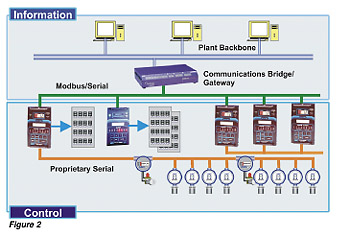
The gas monitoring system must be able to hand off data and accept inputs in the protocol format demanded by the plant-wide control system. In Figure 2 the original single system concept has been expanded to indicate that multiple gas detection controllers might be connected via a serial interface, but the primary Information layer now includes an Ethernet backbone. Now multiple PCs can have access to data from the gas monitoring system. Many other devices will also reside on the backbone, including process control or monitoring equipment, building management devices and control room systems.
Critical to the ability to connect to the plant backbone is the Communications Bridge or Gateway. This device enables hardware platform and protocol conversion interoperability between dissimilar systems and the backbone. The safety professional can breathe a sigh of relief because his choice of monitoring system is no longer restricted to the backbone protocol.
New features
Once the Ethernet interface is established, new features of monitoring systems become available. Possibly the most useful is a Web server function. A Web server can be installed in the Communications Bridge/Gateway or in another Ethernet node so authorized personnel have desktop access to graphical representation of the gas monitoring system status. Graphical representation is no longer relegated to expensive, license-based, control room packages. Other features include report by exception, redundancy functions and remote datalogging, all enabled by the Communications Bridge and accessible via the plant backbone.No heavy lifting here, it is all done for you.
Looking for a reprint of this article?
From high-res PDFs to custom plaques, order your copy today!