Reduce arc flash risks with Condition Based Maintenance
In the U.S. and Canada, the National Fire Prevention Association (NFPA) and Canadian Standards Association (CSA) are at the vanguard of driving a cultural change within the electrical maintenance industry. The NFPA 70E/70B and CSAZ 462/463 standards and guidelines provide references for facilities to meet the requirements of workplace electrical safety and outline the best practices for setting up and maintaining a safe and efficient Electrical Preventative Maintenance (EPM) program.
|
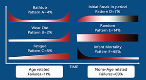
| Figure 1: Failure Patterns Source: IRISS |
Understand equipment failure
When deciding on an electrical maintenance strategy, we first need an understanding of how electrical distribution equipment fails. A valuable resource can be found by reviewing the failure patterns detailed in the Reliability Centered Maintenance (RCM) engineering framework (see Figure 1). These patterns seem to go against common perceptions that age-related failures account for most of the failures seen in the field; in fact, it is quite the opposite. This type of failure only accounts for 11 percent of all the failures seen. The majority of failures are actually due to random failures, which account for 89 percent of system failures. In particular, infant mortality accounts for 68 percent of all failures, dispelling the “it’s brand new so it should be OK” myth.
When we look at the curves in Figure 1, we can see how important it is to try to identify failures as early as possible. To allow us to do this, we need to understand how failures occur and how these failures affect the function of the equipment. To help with this, we use a P-F Curve, which is a curve that represents how equipment fails and how early detection can assist in allowing an organization to plan repairs and avoid business disruption.
Plan for repairs
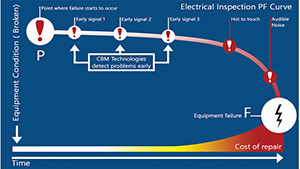
Figure 2 shows an Electrical Inspection P-F Curve. Point P on the curve is where a Physical failure starts to occur, which is an identifiable physical condition that indicates a functional failure is imminent. Point F on the curve is where the point of failure or Functional failure occurs, which is the inability of the equipment, or the assembly containing it, to meet a specified performance standard. An electrical system failing to supply power would be considered a functional failure.
If we use Condition Based Maintenance (CBM) equipment to identify the presence of a failure mode, this then allows us to plan and schedule the work early enough before a total functional failure occurs. Figure 2 shows three stages of early detection at which point the CBM equipment test results would be different, and the equipment readings would change depending on the severity of the faults being monitored.
|
| Figure 2: Electrical Inspection PF Curve Source: IRISS |
Assess equipment
It is recommended that you conduct a thorough assessment of the equipment and systems you wish to inspect before starting a CBM program. RCM practices give an operator several steps that should be considered while conditioning the equipment/system assessment. They are:
1. Functions: Clearly describe Main and Support Functions as well as performance standards we need to maintain.
2. Functional Failures: Describe the inability to maintain specified performance standards.
3. Failure Modes: The specific manner or sequence of events that result in functional failure (What caused the component to fail).
4. Failure Effects: What happens when each failure mode occurs? Events that lead to failure — First sign of evidence — Secondary damage — Action required to return to normal operating condition.
5. Failure Consequences: How does the failure impact your business? (Hidden, EHS, Operational, Non-operational)
6. Develop Maintenance Task: What tasks are best suited to mitigate the failure mode?
7. Reduce Consequences: What can be done to reduce the consequences of failures where there is no scheduled maintenance task? (Consequence Reduction Tasks)
Conducting an RCM analysis will enable you to predetermine the types of Condition Based Maintenance (CBM) inspections that need to be completed to detect failing components such as infrared, ultrasound, ultraviolet scanning, etc.
At this stage, you would also specify the inspection alarm criteria for the CBM equipment and the electrical maintenance safety devices (EMSD’s) that would be required to allow safe access for the CBM inspections to be done while the equipment was energized and loaded (IR Windows, Ultrasound ports, etc.).
Finally, decide what actions the maintenance team will take should any of the CBM inspection alarm levels be breached. This will save a lot of time, stress and effort if the equipment starts to fail, because you would have already decided on the course of action to be taken, allowing for much greater efficiencies in the maintenance and repair process.
Looking for a reprint of this article?
From high-res PDFs to custom plaques, order your copy today!